资源下载
资源下载

使用ESP8266的网络控制伺服电机

文件列表(压缩包大小 97.81K)
免费
概述
需要的元件
- Arduino开发板(任何Arduino)
- 基于ESP8266的开发板(ESP-01)
- Tower Pro SG90伺服电机
- 跳线
- 电阻(1KΩ和2.2KΩ)——1/4W
- 开关
- 滑动开关(SPDT)
- 电脑(或手机)
原理及流程
在本项目中,我们将使用ESP8266来实现Web控制伺服电机,即可以通过网页(在同一个WiFi网络中)控制伺服电机的移动。
总览
伺服电机是行业和DIY项目中最常用的电机之一。在本项目中,我将演示一个基于伺服电机的项目,其中涉及Tower Pro SG90伺服电机和ESP8266 WiFi模块。
我将创建一个带有滑块的简单网页(HTML)。当从与ESP8266连接到同一WiFi网络的计算机或手机访问此网页时,便可以通过调节滑块来控制Servo Motor的位置。
原理
通常,为了使用Arduino控制伺服电机,需要伺服电机、Arduino和电位计。根据输入POT的位置,伺服电动机输入的PWM值会发生变化,因此伺服电动机的轴的位置也会发生变化。
使用ESP8266的Web伺服电机时,仍然使用Arduino驱动伺服电机,但输入不是来自POT,而是来自我们创建的Web页面。
网页中的滑块发送角度值,由充当Web Server的ESP8266接收。ESP8266收到该值后,会将其传输到Arduino,然后Arduino根据该值更改伺服电机的位置。
这里要记住的一件重要事情是服务器和客户端都应该在同一网络上,即充当服务器的ESP8266,作为客户端的计算机(或手机)必须连接到同一网络WiFi网络。
前提条件
ESP8266模块必须使用AT Commands固件进行烧写。有关更多信息,请参阅如何更新ESP8266中的固件。
是使用Arduino控制ESP8266(安装有AT命令固件)。有关更多信息,请参考使用ESP8266和ARDUINO的WIFI控制的LED。
电路图
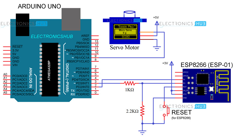
下图为使用ESP8266 WiFi模块的Web控制伺服电机的电路图。
电路设计
Arduino将负责所有的驱动工作,例如将ESP8266连接到WiFi,获取ESP8266的信息并最终控制伺服电机。
为了启用Arduino和ESP8266之间的串行通信,Arduino的Pin 2和3需要被启用为SoftwareSerial(在程序中)。此处,引脚2充当RX,引脚3充当TX。因此,将ESP8266的TX连接到Arduino的引脚2,并将ESP8266的RX连接到引脚3。
电平转换器:ESP8266无法承受5V电压,因此首先使用两个电阻(1KΩ和2.2KΩ)对Arduino的TX(引脚3)进行电平转换,然后将其连接到ESP8266的RX。
ESP8266的VCC,CH_PD和GND引脚分别连接到3.3V,3.3V和GND。ESP的RESET引脚连接到按钮,按钮的另一端连接到GND。
Arduino的引脚9将向伺服电机提供必要的PWM信号。伺服电机其他两个引脚为电源引脚,并分别连接到5V和GND(红色和棕色)。
代码
Arduino代码
下面给出了使用ESP8266项目的网络控制伺服电机的Arduino代码。
#include <SoftwareSerial.h>       //Software Serial library
#include <Servo.h>                //Servo library
SoftwareSerial espSerial(2, 3);   //Pin 2 and 3 of Arduino act as RX and TX. Connect them to TX and RX of ESP8266
#define DEBUG true
#define servoPin 9                //Servo is connected to Pin 9 of Arduino
Servo myServo;                    //variable for servo

int curPos = 90;
int minPos = 10;
int maxPos = 170;

void setup()
{
  myServo.attach(servoPin);
  myServo.write(maxPos);
  myServo.detach();
  Serial.begin(9600);
  espSerial.begin(115200);

  espData("AT+RST\r\n", 3000, DEBUG);                      //Reset the ESP8266 module
  espData("AT+CWMODE=1\r\n", 3000, DEBUG);                 //Set the ESP mode as station mode

  /* In the next command, enter your WiFi Network name in place of SSID and
  password in place of PASSWORD*/

  espData("AT+CWJAP=\"SSID\",\"PASSWORD\"\r\n", 3000, DEBUG);   //Connect to WiFi network

  while(!esp.find("OK"))
  {
      //Wait for connection
  }
  delay(3000);

  espData("AT+CIFSR\r\n", 3000, DEBUG);          //Show the IP address

  /* The following statement is to assign Static IP Address to ESP8266.
  The syntax is AT+CIPSTA=<ip>,<gateway>,<netmask>.
  This will assign a Static IP Address of 192.168.1.254 (in my case)
  to the ESP8266 Module. Change this value as per your requirements i.e. this IP address
  shouldn't conflict with any other device.
  Also, the second and third parameters are Gateway and Net Mask values.
  You can get these values from ipconfig command in command prompt*/

  espData("AT+CIPSTA=\"192.168.1.254\",\"192.168.1.1\",\"255.255.255.0\"\r\n", 3000, DEBUG); // Assign Static IP Address
  //AT+CIPSTA="192.168.6.100","192.168.6.1","255.255.255.0"

  espData("AT+CIPMUX=1\r\n", 3000, DEBUG);       //Allow multiple connections
  espData("AT+CIPSERVER=1,80\r\n", 3000, DEBUG); //Start the Web Server on port 80
}

void loop()
{
  if (espSerial.available())     //check if there is data available on ESP8266
  {
    if (espSerial.find("+IPD,")) //if there is a new command
    {
      String msg;
      espSerial.find("?");                           //run cursor until command is found
      msg = espSerial.readStringUntil(' ');          //read the message
      String command = msg.substring(0, 5);    //command is informed in the first 5 characters "servo"
      String angleStr = msg.substring(6);      //next 3 characters inform the desired angle
      int angleValue = angleStr.toInt();            //convert to integer
      if (DEBUG)
      {
        Serial.println(command);
        Serial.println(angleValue);
      }
      delay(100);
      //move servo to desired angle
      if(command == "servo")
      {
         //limit input angle
         if (angleValue >= maxPos)
         {
           angleValue = maxPos;
         }
         if (angleValue <= minPos)
         {
           angleValue = minPos;
         }
         myServo.attach(servoPin); //attach servo
         while(curPos != angleValue)
         {
           if (curPos > angleValue)
           {
             curPos -= 1;
             myServo.write(curPos);
             delay(10);
           }
           if (curPos < angleValue)
           {
             curPos += 1;
             myServo.write(curPos);
             delay(10);
           }
         }
         myServo.detach(); //dettach
      }
  }
  }
  }
String espData(String command, const int timeout, boolean debug)
{
  String response = "";
  espSerial.print(command);
  long int time = millis();
  while ( (time + timeout) > millis())
  {
    while (espSerial.available())
    {
      char c = espSerial.read();
      response += c;
    }
  }
  if (debug)
  {
    Serial.print(response);
  }
  return response;
}
网页的HTML代码
为了创建一个简单的网页,我使用了以下HTML代码:
<!DOCTYPE html >
<html>
<head>
<title>Web controlled Servo</title>
<script src="myjquery.js"></script>
</head>
<body>
<h2> <b> Web Controlled Servo using ESP8266 </b> </h2>
<h3> Slide to move the Servo </h3>
<input type="range" min="10" max="170" onmouseup="myservo(this.value)" />
</body>

<script>
$.ajaxSetup({timeout:1000});
function myservo(angle)
{
    IPVar = "192.168.1.254";
    ArduinoData = "http://" + IPVar + ":80";
    $.get( ArduinoData, { "servo": angle })    ;
    {Connection: close};
}
</script>
</html>
注意:为了使用此HTML代码创建网页,请将扩展名为.html的代码保存在一个文件夹中,并在同一文件夹中放置“ myjquery.js”文件,你可以从下载区下载该文件。
使用ESP8266进行Web伺服控制
按照电路图进行所有连接后,将Arduino代码上传到Arduino UNO。
上载代码后,如果打开串口监控器,就可以看到ESP8266 WiFi Module的状态。
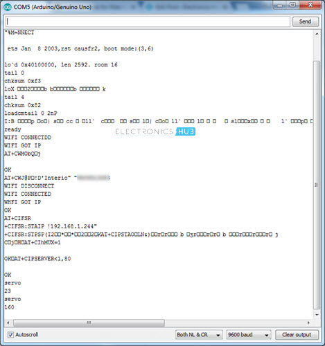
完成所有初始化步骤后(将模式设置为Station模式,将ESP连接到WiFi,设置静态IP并启动Web服务器),即可继续进行Web控制。
现在使用任何Web浏览器打开HTML文件,浏览器将显示一个指示项目的简单文本。在其下,你可以看到一个滑块。
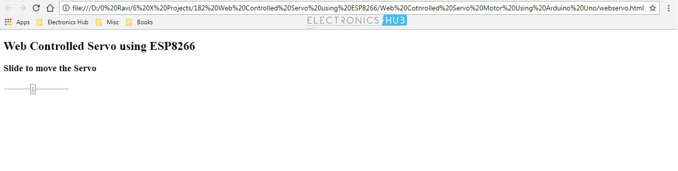
如果一切正常,则更改滑块的位置时,伺服电机的位置也会发生变化。
应用领域
使用ESP8266进行网络控制的伺服器的想法是实现网络控制的设备(在本例中为伺服电机),即通过互联网控制电机。该应用程序可以进一步扩展到更高级和更复杂的项目,例如从Internet控制机器人等。
最后
所有需要的文件在下载区均可找到。
via:https://www.electronicshub.org/web-controlled-servo-using-esp8266/
理工酷提示:
如果遇到文件不能下载或其他产品问题,请添加管理员微信:ligongku001,并备注:产品反馈

评论(0)

0/250